
Energy and furnace technology
Laboratory facilities at the Unit of Process that support studies in high temperature experiments kinetics include many custom-built and customised furnaces, chemical preparation facilities and measurement devices.
Small-scale High Temperature Air Combustion (HiTAC) furnace
Investigations may be done under a large variety of conditions, such as different gas compositions (mixture of N2, O2, CO2 and H2O), temperature and velocity of inlet gas.
To meet requirements of investigation the small test stand facility is equipped with following parts:
- Supply gas system
- Heating up system
- Small furnace/combustion chamber
- Temperature stabilization system
- Measurement and data acquisition system
The gas delivery system includes the following gas lines:
- Oxidizers: air, oxygen
- Fuels: LPG (mainly propane), natural gas (mainly methane)
- Additional gases: nitrogen, carbon dioxide
Each line consists of fan or set of cylinders (compressed air or liquid phases), control and measurement unit, stop valve and line connections.
Heating up system includes burner, oxy-burner and SAI-preheater. During normal operation only one of them is used. Conventional burner produces flue gases in wide range of excess air and temperature level in firing rate from 10 kW to 100 kW.
Small furnace consists of few sections:
- Burner section
- Additional gases section
- Temperature stabilization section
- Test chamber
- Chimney section
Main construction is made up of steel. The furnace walls are isolated with a 0.3 kWm layer ceramic and glass fibre material. In temperature stabilization section the flue gases are cooled by the use of air heat exchanger, to give stable temperature, independent on excess air and firing rate of the burner. The main section of furnace, test chamber, can be changed for different applications, for example in studying single fuel jet combustion the combustion chamber with co-flow or cross-flow fuel nozzle is used. This section is therefore equipped with quartz glass windows, which enable to make optical investigation.
During investigation of single flame combustion, it is possible to do following:
- Temperature distribution measurements
- Heat flux distribution measurements
- Gas composition distribution measurements
- Velocity field measurements
- Optical and spectroscopic observation
Semi-industrial scale High Temperature Air Combustion (HiTAC) furnace
This furnace is built to validate the results from the small-scale HiTAC furnace and demonstrate the scalability of results. The reactor can be used to investigate ways to reduce the emission of \(\mathrm{NO}_{x}\), increase heat transfer efficiency to allow downsizing of existing furnaces or upscaling of small-scale processes.
The furnace may be fitted with different high-cycle regenerative systems (HRS) as well as an Oxy-fuel system and a conventional heating system. The HRS systems are equipped with "honeycomb" regenerators to provide the necessary hot combustion air and recover heat.
Furthermore, the test furnace is equipped with two different flue gas channels. One of these is for hot flue gases equipped with water-cooling jacket, others are for cold flue gases coming from the regenerators (HRS directly). The flue gas channel for hot gases allows the furnace to be run in conventional mode. In addition, it can also be used when the flue gas suction rate, in case of HiTAC, is below 100%, in which some of the flue gases have to be extracted through the hot flue gas channel.
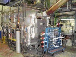
The nominal capacity of the furnace is 500 kW, the inner dimensions of the furnace body were 3.5 × 2.2 × 2.2 m. The furnace body is insulated with a 0.3 m thick layer of ceramic fiber material. There is also a number of openings in the furnace body for observations and measurements inside the combustion chamber.
The following different burning systems can be installed to the furnace for combustion process investigation:
Burning systems can be fired with different gas fuels having different fuel calorific value and composition. Up to date, liquid propane gas (LPG) is used. The possibilities for natural gas firing would be there in the near future.
To provide a wide range of flow and pressure required by a variety of heat recovery systems, frequency converters control the fans of the draft system, forced and induced fans.
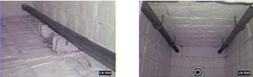
The heat is taken away from the furnace by four horizontal cooling tubes made of a special temperature resistant kanthal alloy. The pipes were cooled with air and provide a large range of load to be removed from the furnace.
High Temperature Air and Steam Gasification (HTAG) reactor
This bespoke reactor can be operated continuously and uses preheated air as the gasifying agent and can achieve preheat temperatures of up to 1600 ℃, thanks to a modern high-cycle regenerative air/steam preheater. The flow of preheated air can be up to 110 Nm3/h. This preheated air provides additional energy to the gasification process and enhances thermal decomposition of the solids. It has been demonstrated that clean fuels may be produced using this furnace.
High Temperature Air Gasification (HTAG)/High Temperature Air Combustion (HiTAC) mini test facility
This facility has recently been built up to perform batch type, small scale combustion and gasification tests.
The rig is more or less 1 meter in length horizontal combustion chamber with its inner diameter about 0.1 m. During the heating up state the fuel gas and air feed the gas burner through which the combustion chamber heats the ceramic honeycomb. The flue gases from the honeycomb through the second part of the combustion chamber go to facility’s outlet. During the experiment state (when the gas burner is off) the air or mixture of air and nitrogen (or steam) is heated by hot honeycomb to reach the proper temperature which is measured by the thermocouple.
The special constructed basket with biomass, which is not shown at this scheme, is put in by special screw, into the small bucket and it is constantly cooled by nitrogen. During the investigation to the combustion chamber in this manner, it can be seen through the glass opening. The composition and temperature of flue gases after biomass combustion is measured by thermocouple and gas analysis probe. After certain time of experiment the basket is taken out first to the small bucket and after certain time, which is necessary because of cooling purposes, is removed from the rig. Also through the glass opening the ignition phenomena can be observed by a digital camera.
Diagnostic Equipment
HTAG test facility
Data acquisition system basically made up by a Keithley Multimeter 2701 equipped with two Multiplexes 7708. Each Multiplexer has 40 channels, which can measure voltage, resistance or current. That makes easy to connect the multimeter with thermocouples, pressure meter as well as with output signal from gas analyser or flow meter units. Multimeter 2701 is equipped with TC/IP connection with separated IP address.
Set of flow meters and pressure regulators to control flow rate of air and steam.
A set of thermocouples for temperature measurement.
Micro Gas Chromatograph configured with four independently controlled modules to measure the fuel gas composition. The micro-GC is connected to a desktop computer used in combination with EZChrom 400/RGA (version 4.5) software as a chromatography data analysis station and storage device. With cycling time (sampling and analysis) ranging from 50 to 160 seconds, the following chemical species are measured by the microGC: H2, CO, CO2, O2, N2, CH4, C2s, C3s, C4s, C5s, and some higher hydrocarbons grouped and called C6+.
Gas analyser equipped with two ZrO sensors, one for dry and another for wet oxygen measurements; non-dispersive infrared spectroscopy for CO and CO2 measurements, and a Humox designed to calculate volume concentration of H2O-based on the measurement of O2 wet and dry. The gas analyser is used either for fuel gas or for flue gas characterisation.
Sampling and analysis of tars is achieved, using the solid-phase adsorption (SPA) method, developed in laboratory of the Department of Chemical Engineering and Technology, Chemical Technology, Royal Institute of Technology (KTH). This method is suitable for intermittent trapping of tar compounds ranging from benzene to coronene prevailing in product gases from thermal decomposition of biomass at 700 ℃ to 1000 ℃.
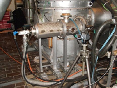
HiTAC test furnace
The HiTAC furnace body has an extensive set-up of different measurement systems including several measurement points for temperature, pressure and flow rates. The aim of these measuring equipments is to visualize the temperature in any place inside the furnace, energy and mass balance of test furnace and energy and mass balance of regenerators.
Mapping the furnace from inside for the heat flux and flue gases composition is also possible. In addition to the some basic instrumentation, such as flow meters and pressure meters, the following diagnostic equipment are available:
Temperature measurements: more than 120 thermocouples are used to measure furnace wall temperature at different locations, radiant tube temperature profile, flue gases and air temperatures for furnace and regenerators energy balance calculations. They are mainly K-type, S-type and R-type thermocouples.
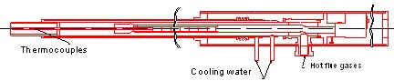
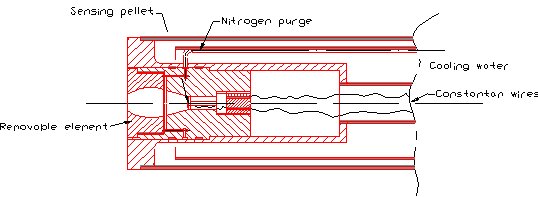
Water-cooled Suction Pyrometer: for safe and more accurate measurement of gas temperatures at any point inside the furnace. The probe is manufactured by (IFRF) in Holland.
Water-cooled Radiation Heat Flux Probe (RHF): The radiation pyrometer is used to measure the total heat flow due to the radiation falling the tip of the probe inserted in the furnace. The radiation pyrometer is constructed to neglect convective heat transfer to the sensor from the furnace.
Water-cooled Total Heat Flux Probe (THF): The Total heat flux meter is a conductivity plug-type heat flow meter. The instrument measures the total heat flow, both convection and radiation that is absorbed by it's receiving surface. It is also manufactured by (IFRF) in Holland.

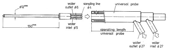
Flue Gas Sampling and Conditioning: the figure below shows the water-cooled sampling probe that can be inserted inside the furnace using the computer controlled traversing system. The sampling and conditioning system is not only designed to ensure the gas sample has the same composition at the analyser inlet as that at the beginning of sampling but also to consider the dynamic influence caused by the operation nature of HRS.
Micro GC: consists of 4 different modules and each module consists of analytical column, TCD and other GC components. The micro GC can detect and quantify CO, CO2 O2, N2 and CxHy up to C8 at any point inside the furnace with a very short time, down to 35seconds.
NOx Chemiluminescence analysers: Measures NOx emissions out of combustion.
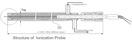
Ionization probe: It is used to study the structure of HiTAC flame and to measure the ion current in the flame as a judgment of existing position of HiTAC flame, which is transparent flame.
Data acquisition: manufactured by NI, USA and Keithely, USA. These systems are able to log up to 200 input voltage or amperage signals. Some modules are capable to provide output signals for controls.